
Ultrasonic Parking Project
Project Code and Circuit
8/23/20252 min read
Build Your Own Ultrasonic Parking Sensor! 🚗
Tired of bumping into things while parking? Or maybe you're just looking for a cool, simple project to get started with electronics? Well, you're in luck! Today, we're going to build a mini parking sensor using a few common components. It's a fun and practical way to understand how ultrasonic sensors work.
What You'll Need
Here's the shopping list for our project. Don't worry, all these parts are super easy to find online or at your local electronics store.
Arduino UNO: The brain of our operation! This is a micro-controller that we'll program to read the sensor and control the buzzer.
Ultrasonic Sensor (HC-SR04): This is our "eyes." It uses sound waves to measure distance, just like a bat!
Buzzer: Our "ears." It will make a sound to let us know how close an object is.
Jumper Wires: These are the "nerves" that connect everything together.
Breadboard (optional but helpful): A great tool for connecting components without soldering.
How It Works: The Magic of Sound
The project is based on a simple principle: echolocation.
The ultrasonic sensor sends out a high-frequency sound pulse. Think of it as a quick "ping!" that we can't hear.
This sound pulse travels through the air and bounces off the nearest object (like a wall or another car).
The sensor then listens for the echo to return.
By measuring the time it takes for the sound to travel out and back, the Arduino can calculate the distance to the object. It's using a simple formula: Distance = (Time × Speed of Sound) / 2. We divide by two because the sound has to travel to the object and back.
Based on this calculated distance, our Arduino will tell the buzzer what to do. The closer the object gets, the faster and more frequent the beeps become, just like a real parking sensor!
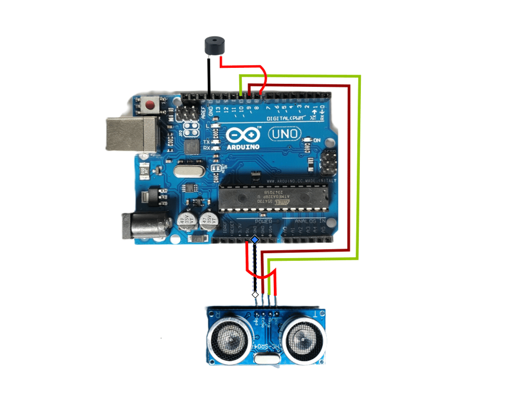
Let's Get Wired! 🔌
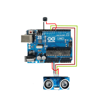
Connecting the components is straightforward. Refer to the image at the top of this post for a visual guide.
Connect the VCC pin of the ultrasonic sensor to the 5V pin on the Arduino. This gives the sensor power.
Connect the GND pin of the sensor to the GND pin on the Arduino. This completes the circuit.
Connect the Trig (Trigger) pin of the sensor to Digital Pin 9 on the Arduino. This pin sends the sound pulse.
Connect the Echo pin of the sensor to Digital Pin 10 on the Arduino. This pin listens for the echo.
Finally, connect the positive (+) pin of the buzzer to Digital Pin 12 on the Arduino and the negative (-) pin to GND.
Simply copy and paste this code into the Arduino IDE, connect your Arduino to your computer, and click "Upload."
The Code 💻
Now for the fun part: giving our project instructions! You'll need to upload a sketch (the code) to your Arduino. The code below is a basic example.